- Home
- Principles and Practices
- Computer Aided Design
- Computer Controlled Cutting
- Electronics Production
- 3D Scanning and Printing
- Electronics Design
- Molding and Casting
- Embedded Programming
- Computer Controlled Machining
- Input Devices
- Composites
- Interface and Application Programming
- Output Devices
- Networking and Communication
- Mechanical/Machine Design
- Applications and Implications
- Invention, Intellectual Property, and Income
- Project Development
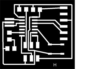
This weeks project is to (re)design a hello echo board. Not only are we redesigning this circuit board, but we are also adding more components to it. The components that I added were a 499 ohm resistor, a LED, and a button. Using Eagle editing software, I added my components of the hello echo board in a schematic and board view:  Next I used the trace and outline image from the board view in Eagle to upload that .stl file into Gimp which is a vector and raster based editing software. I also used Gimp to export my files as .png files so that the Roland Modela would read them. I uploaded both images (traces and outline) into the Roland Modela software and once the machine was set to run, I milled my hello echo board: After the board was milled, I gathered all of my necessary components and soldered them to my hello echo board. Since I started the course late, this was my first soldering job. It went smoother than I expected, so I thought. I felt improved after this soldering experience job. I also gained good experience in design by using Eagle design software and Gimp editing software. The Roland Modela milling machine allowed me to get comfortable with completing a project on my own without the help of my instructor. The purpose of this assignment is to get us comfortable with redesigning circuit boards and programming them to suit our (the designers) specific needs of the computer. I am slowly gaining enough confidence to increase the difficulty level of my design and programming projects. |